Surface paths: Deburring
Introduction
This topic will explain the options found in the Surface paths tab of the Deburring operation.
Surface paths
The Surface paths tab allows you to define the part and check surfaces, the path parameters, Extensions and overlaps, as well as the surface quality of the toolpath.
Geometry input
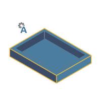
- Part surfaces - determines the edges to be machined and uses these same surfaces as check surfaces.
Important: Surfaces must be selected for this operation. Additional surfaces may be checked for collision detection with the Check surfaces option.
- Edge definition
- Auto detect - The system attempts to find all edges to deburr.
- User defined - allows you to select specific edges to deburr.

- Auto detect - The system attempts to find all edges to deburr.
Advanced auto edge detection
With the Edge definition set to Auto detect, click the Advanced button to launch the Advanced option for Port Machining Area dialog.
-
Minimal edge angle - allows you to set an angle range to ignore. Angles under the value entered are ignored.

-
Minimal detected edge length

 - Lengths of the edges are ignored as a factor.
 -
A value can be entered in order to ignore edges whose lengths are less than the specified value.
-
A value can be entered in order to ignore edges whose lengths are less than the specified value.
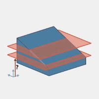
- Limit detection area by height

- Lengths of the edges are ignored as a factor. -
A value can be entered in order to ignore edges whose lengths are less than the specified value. - Reference axis - opens the Line dialog which allows you to define a direction in which the area will be limited.
Line
-
 By start point and end point - allows you to either enter values for the start and end points, or select a line to define those points.
 -
 By base point and direction - allows you to specify a direction in which the area will be limited.
-
Base point - Select between Center to use the center of the geometry of a User defined point.
-
Direction - Select between User defined direction or standard X,Y,Z axes in order to define the direction of limitation.
-
-
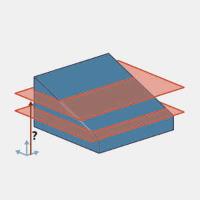
Start - defines the distance from the machine setup to start the first limiting plane.
-
End - defines the distance from the machine setup to end the other limiting plane.
- Include unsharp edges

- edges that cannot be determined to be sharp on the model are ignored. -
This feature deburrs the edges that cannot be determined from the input mesh using the "edges sharper than an angle" threshold. The relevant edges might already be rounded or already chamfered in the input mesh. This new option detects the edges as if they were sharp edges.
-
Exclude edges - With the Edge definition set to Auto detect, this allows you to select edges which should not be machined by this operation.
- Check surfaces
- Allows you to select additional surfaces which are considered for collision checking in the toolpath calculation. Collision avoidance depends on the selected tilting strategy. For example, if the selected strategy is 3-axis, any contact between the check surface and the tool will be avoided by trimming the affected toolpath segments. If the tilting is set to 5-axis, the system first tries to tilt the tool away from the check surfaces and uses trimming as if tilting no longer helps. Check surfaces are typically fixtures or clamping systems that interfere with machining. - The toolpath is not checked against additional surfaces.

-
Check surfaces clearance - When the Check surfaces options is used, this value specifies the distance from the specified surfaces to use as the clearance amount.

Path parameter
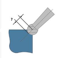
- Edge shape - defines the type of edge to be cut.
- Constant width - specifies that the distance between the edges and the edges of the chamfer is constant.
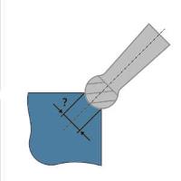
- Constant depth - specifies that the distance is defined from the center of the ball mill cutter.
- Constant radius - uses the radius of the edge fillet for round multiple cuts.
- Constant width - specifies that the distance between the edges and the edges of the chamfer is constant.
Note: Constant radius is only available when the Number of cuts along edges value is more than 1, and the option is set to Rounded.
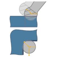
- Inner corners - allows you to define how the interior corners are cut. Choose between:
- Trim - removes the portion of the toolpath which would create a relief cut in the corner.

- Relief - continues into the corner of the part creating a relief cut.
- Trim - removes the portion of the toolpath which would create a relief cut in the corner.
Note: Relief cuts lead to a smoother transition between the specified area that can be machined and the areas that cannot be reached by the tool in the inner corners.
Important: Relief grooves are only applied to inner corners with equal edge angles on both sides of the inner corner.
Advanced
When the Relief option is used for Inner corners, you can insert a loop movement into those relief cuts.
- Add loops to relief cuts
- no loops are added to the relief cut. -
This feature deburrs the edges that cannot be determined from the input mesh using the "edges sharper than an angle" threshold. The relevant edges might already be rounded or already chamfered in the input mesh. This new option detects the edges as if they were sharp edges. - Loop radius - defines the size of the loop in the relief cut.

-
Direction - With the Machining type option in the Tilting group of the Tool axis control page set to any of the 3 or 4 Axis options, you can choose between Climb or Conventional.
-
Number of cuts along edges - allows you place more than one cut along a sharp edge to approximate the flat (chamfer) or rounded (fillet) shape of the edge.


Extensions/Overlap
-
Length - specifies the distance to add to the beginning and end of each toolpath segment.
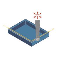
Important: Extensions are created tangentially to the respective start/end of the toolpath segment. When the segment is connected to another segment tangentially, the extension is created along the connected segment and there is an overlap. This behavior occurs in particular on segments that are close to each other.
Surface Quality
-
Cut tolerance - specifies the allowable deviation from the target geometry.
